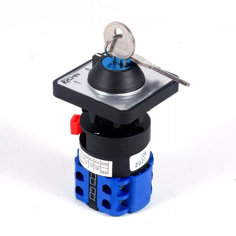
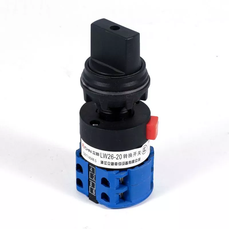
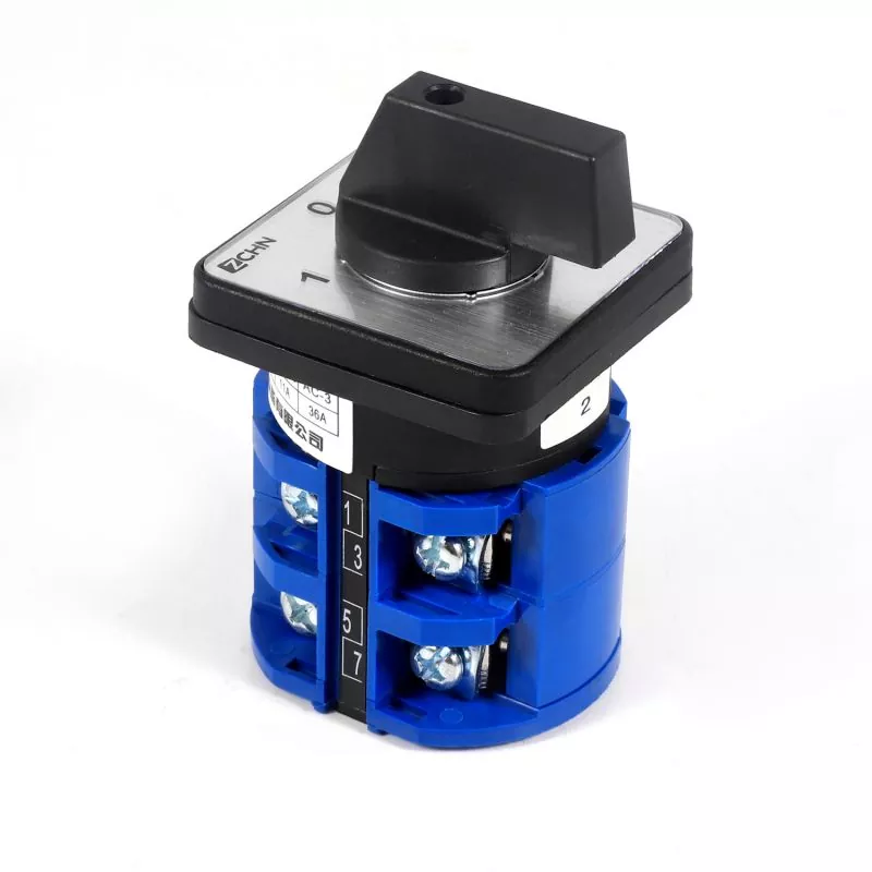
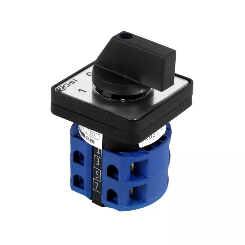
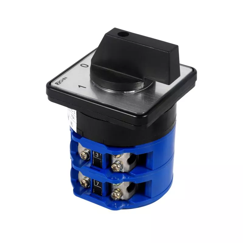
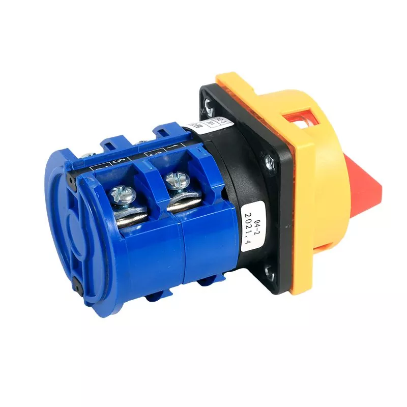
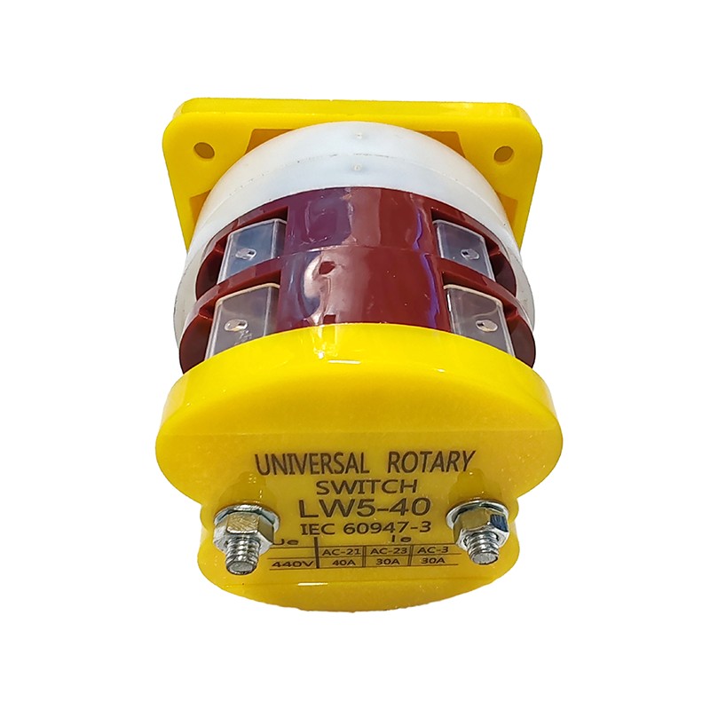
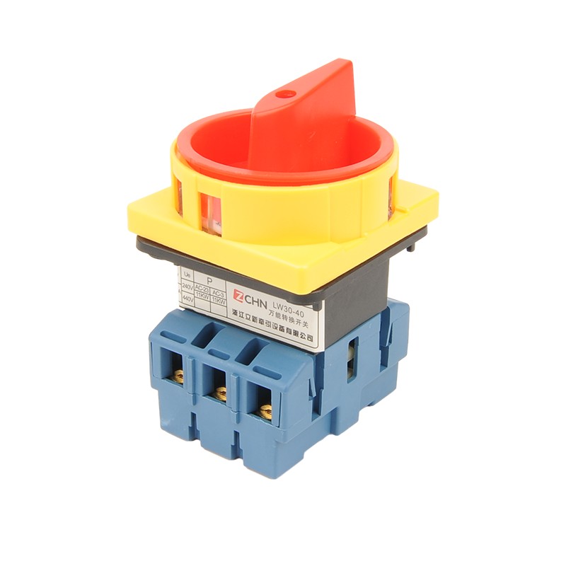
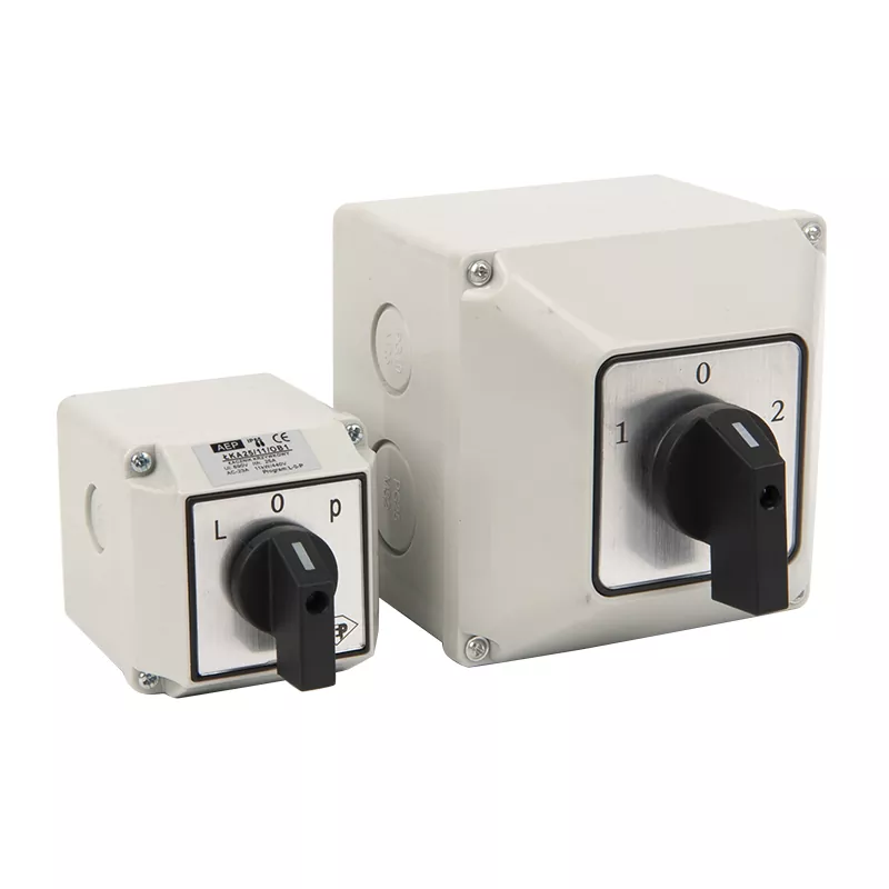
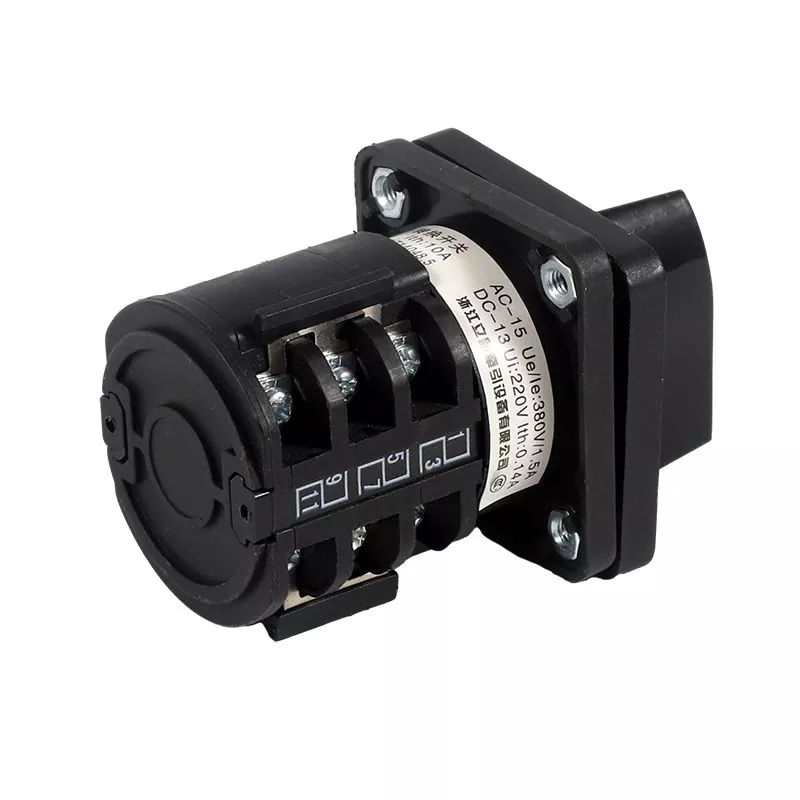
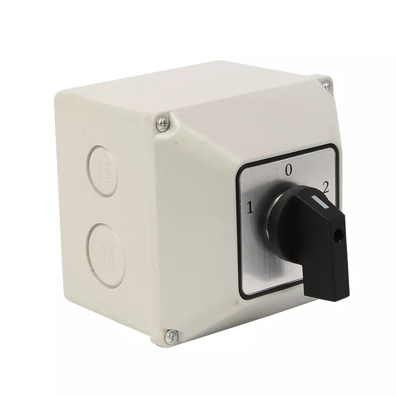
SZW26-20/D303.3 Cam Switch
Send Inquiry
The SZW26-20/D303.3 cam switch is a specific model within the LW26 series of rotary cam switches. Here's an overview of its features and specifications:
Model: SZW26-20/D303.3
Current Rating: The "20" in the model number typically indicates a current rating of 20A, meaning it can handle a maximum current of 20 amps.
Voltage Compatibility: It is suitable for both AC and DC voltages. Specific voltage ratings can vary depending on the model and application requirements.
Certifications: The SZW26-20/D303.3 cam switch is likely certified to meet industry standards such as GB/T 14048.3, GB/T 14048.5, and potentially international standards like EN60947-5-1.
Safety Features: Like other switches in the LW26 series, it may include safety features such as finger protection to ensure safe operation.
Applications: This cam switch can be used in various applications, including circuit control, testing equipment, motor control, and primary command control. It is particularly suitable for applications requiring speed adjustment or precise control.
Overall, the SZW26-20/D303.3 cam switch offers reliable performance and flexibility in controlling electrical circuits, making it a versatile component in industrial and commercial settings.
|
Controls way |
trait designation |
Actuator position |
|||
|
Self-replicating type |
A |
0°30° |
0-45° |
0°-60° |
|
|
B |
30°-0°30° |
45°0°-45° |
60°0°-60° |
||
|
X |
60-30=0°30-60° |
||||
|
Locating type |
C |
0°30° |
0°45° |
0°60° |
|
|
D |
30°0°30° |
45°0°45° |
60°0°60° |
||
|
E |
30°0°30°60° |
45°0°45°90° |
60°0*60*120° |
||
|
F |
60°30°0°30°60° |
90°45°0°45°90° |
60°0°60°120°180° |
||
|
G |
60°30°0°30°60°90° |
90°45°0°45°90°135° |
120°60°0°60°120°180° |
||
|
H |
90°60°30°0°30°60°90° |
135°90°45°0°45°90°135° |
|||
|
90°60°30°0°30°60°90°120° |
135°90°45°0°45°90°135°180° |
||||
|
J |
120°90°60°30°0°30°60°90°120° |
||||
|
K |
120°90°60°30°0°30°60°90°120°150° |
||||
|
L |
150°120°90°60°30°0°30°60°90°120°150° |
||||
|
M |
150°120°90°60°30°0°30°60°90°120°150°180° |
||||
|
N |
45° 45° |
30°30° |
|||
|
P |
90°0°90 |
||||
|
T |
0*90° |
||||
|
V |
90°0° |
||||
|
R |
270°0°90°180° |
||||
|
orientation Self-replicating type |
Q |
30°0°-30° |
45-0°45° |
||
|
S |
30°-0°60° |
90°0°-45 |
|||
|
W |
90-45°0°45-90° |
||||
|
Z |
120°-90°0⁰-30° |
135°-90°0⁶-45° |
Lixin 3 Position On-off-On Rotary Cam Switch Type specification
|
Type specification |
LW26-10 LW26-10G LW26-10X |
LW26-20 LW26-20X LW26-20C |
LW26-25 |
LW26-32 LW26-32F |
LW26-40 LW26-40F |
LW26-63 LW26-63F |
LW26-125 |
LW26-160 |
LW26-250 |
LW26-315 |
|
Ui V |
660/690 |
660 |
660 |
660 |
660 |
660 |
660 |
660 |
660 |
660 |
|
Ith A |
10 |
20 |
25 |
32 |
40 |
63 |
125 |
160 |
250 |
315 |
|
Ue V |
240440 |
24110240440 |
24110240440 |
240440 |
240440 |
240440 |
240440 |
240 440 |
240440 |
240440 |
|
le |
||||||||||
|
AC-21A AC-22A A |
1010 |
20 20 |
25 25 |
32 32 |
63 63 |
100 100 |
150 150 |
200200 |
315 315 |
|
|
AC-23A A |
7.57.5 |
15 15 |
22 22 |
30 30 |
37 37 |
57 57 |
90 90 |
135 135 |
265 265 |
|
|
AC-3 A |
5.55.5 |
11 11 |
15 15 |
22 22 |
30 30 |
36 36 |
75 75 |
95 95 |
110 110 |
|
|
AC-4 A |
1.751.75 |
3.5 3.5 |
6.5 6.5 |
11 11 |
15 15 |
30 30 |
55 55 |
95 95 |
||
|
AC-15 A |
2.51.5 |
5 4 |
8 5 |
14 6 |
||||||
|
DC-13 A |
12 0.40.4 |
20 0.5 0.5 |
||||||||
|
Rated control power P |
||||||||||
|
AC-23A KW |
1.8 3 |
3.7/2.5 7.5/3.7 |
5.5/311/5.5 |
75/415/75 |
185/918.5/9 |
15/1030/18.5 |
30/1545/22 |
37/2275/37 |
75/37132/55 |
|
|
AC-2 KW |
2.53.7 |
4 7.5 |
5.5 11 |
75 15 |
185 30 |
30 45 |
37 55 |
55 95 |
||
|
AC-3 KW |
1.52.2 |
3/22 5.5/3 |
4/3 7.5/3.7 |
55/411/5.5 |
15/7.515/7.5 |
11/618.5/11 |
15/7.530/13 |
22/1137/18.5 |
37/2255/30 |
|
|
AC-4 KW |
0.370.55 |
0.55/0.751.5/1.5 |
1.5/1.13/2.2 |
27/1.555/3 |
55/2475/4 |
6/312/5.5 |
10/415/7.5 |
15/7.525/11 |
Lixin 3 Position On-off-On Rotary Cam Switch Normal working condition
1. The ambient air temperature must remain within the range of -25°C to +40°C, with a 24-hour average not exceeding 25°C.
2. The lower limit of the ambient air temperature should not drop below -25°C.
3. Installation locations should not exceed an altitude of 2000m above sea level.
4. At maximum temperature conditions of +40°C, the relative humidity of the air should not exceed 50%. Higher relative humidity levels may be permissible at lower temperatures, such as reaching 90% at 20°C. Special precautions must be taken to mitigate condensation resulting from temperature fluctuations.
Lixin 3 Position On-off-On Rotary Cam Switch Installation condition:
1. The switch is installed in an environment with pollution level 3 conditions.
2. Installation should be carried out according to the instructions provided by our factory.
Lixin 3 Position On-off-On Rotary Cam Switch sort:
1 Divided by use
(1) Switch for main circuit conversion;
(2) Transfer switch for direct control of the motor; (3) Transfer switch for master control and measurement.
2 According to the operation mode
(1) Positioning type;
(2) self-replicating type;
(3) Positioning self-replicating type.
3 According to the contact system
(1) The positioning type switch has 1 to 12 sections (only 8 sections for 63A and above switches);
(2) The self-restoring type transfer switch has 1 to 3 sections (LW26-20; Verses 1 to 8)
(3) The transfer switch for direct control of the motor mainly has 1 to 6 sections.
Lixin 3 Position On-off-On Rotary Cam Switch Overall dimensions and mounting dimensions:


